4 spin welding tips to think about
Published by
Jason Dornbos
on
Spin welding is a really good method for joining thermoplastics. It’s easy to understand, the tooling is simple, the strength results are impressive, and the process is really robust. However, keeping those results consistent and managing weld flash control can be a challenge. As you consider implementing spin welding, here are a few things to think about and watch out for:
1. Don’t limit the consideration of spin welding to round parts!
We all know that the spin weld joint needs to be concentric, but the mating parts don’t have to be round. Sounds fundamental, sure, but it’s easy to categorize things in our minds in such a way that we inadvertently restrict options.
Don’t restrict the process to medium and large parts, either. I recall tooling up a very small check valve for spin welding because the original process of ultrasonic welding was not consistently sealing. This Nylon part had a molded elbow feature which the welding horn had to be relieved for. The area below the horn relief was understandably, inconsistently sealing. The valve was approximately 1” in diameter. With minor weld joint changes, spin welding worked great, problem solved!
2. Design a smart weld joint.
One of the reasons spin welding works so well is that it involves a lot of plastic–surface area, in the weld joint. The process produces strong welds…it also generates quite a bit of flash. Flash is displaced plastic, a byproduct of the welding process. Design a suitable joint for spin welding with a calculated flash trap; don’t use an ultrasonic or vibration welding joint design, this is a very different method. Even though spin welding may work with those types of joint designs, you probably won’t be pleased with the results.
3. Design sufficient features into the parts to orient and drive one part and to consistently secure the other part.
For spin welding to work well, there needs to be intentional ‘drive lugs’ or distinct molded features in the part that will be driven. The spin weld drive tooling will be machined to align with these drive features. Treat these molded details as you would any other controlled dimension on the part.
Serious torque is transferred through the weld joint and into the fixtured component. As in the driven part, be certain to either mold in ‘grip’ features or to identify suitable molded details so that the fixture can consistently locate and support the part.
Measure and control these molded features as you would with other critical dimensions of the components.
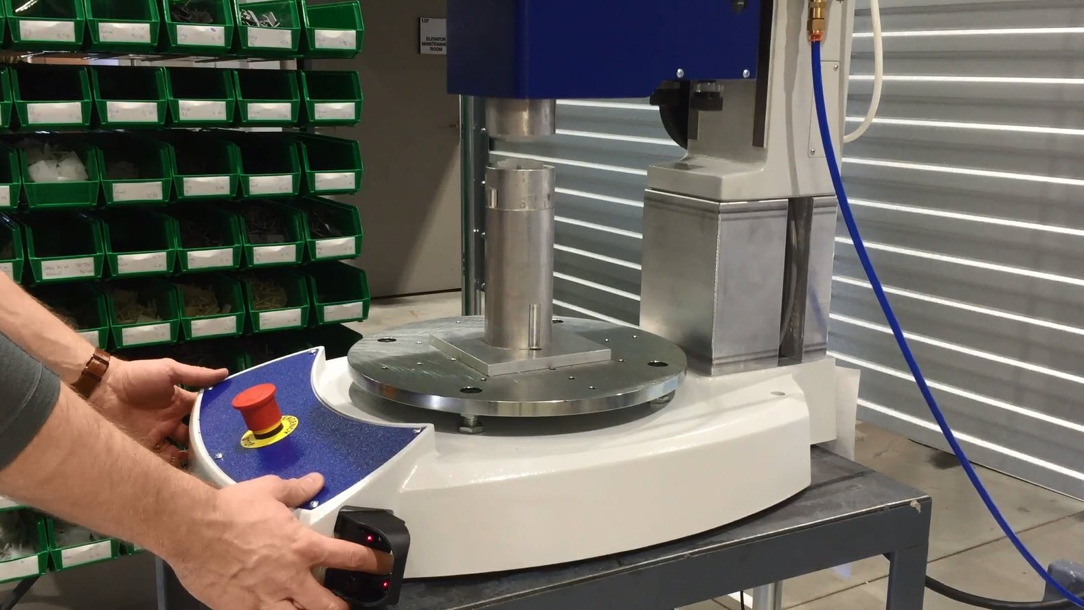
4. Invest in a spin welder that is equipped with capability and technology.
Some people have a less-than-favorable opinion of spin welding because of what spin welding machines used to be. They used to be everything from a modified drill press to a clunky, pneumatically driven, clutch controlled, wonder machine.
These days, servo-driven welders with force and velocity control and the ability to weld by depth are widely available – and they are worth the investment! Welding components together with a tightly controlled RPM, within 1-degree of a programmed rotation, and with the assurance of a certain displacement within the joint are very good things.
Explore the potential of spin welding for your thermoplastics today! Need advice on whether or not a spin welding machine is best for your application? Our team of experts is ready to assist you. Reach out now by using the contact form below!
Tags:
Spin Welding